


Machine vision is a new field. It can reduce process inefficiency with correctly setting up. Any facility that uses machine vision as a robot to guide or inspect should pay attention to this field and seek possible improvements. Machine vision system might lead to non-value-added downtime if it was not proper set up. Here are ten aspects that should be paid attention to machine vision improvement.
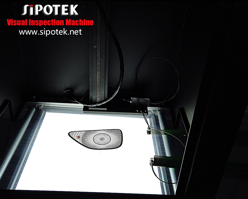
- Lighting technology
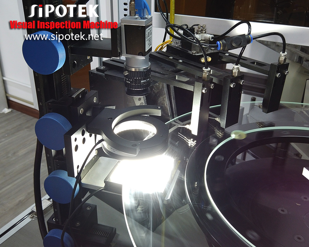
The correct lighting technology should be used to illuminate the inspected area. Lighting techniques such as back lighting, bright field, glancing, low-angle linear arrays, and dark fields are the most critical aspects of machine vision. Depending on the surface finish and contour of the part, the correct lighting technology can enhance defects or remove image noise, improving system efficiency and stability. It is aim to choose a lighting technique that produces maximum contrast (from black to white pixels). In addition, the contrast needs to be directly related to what is being measured or checked.
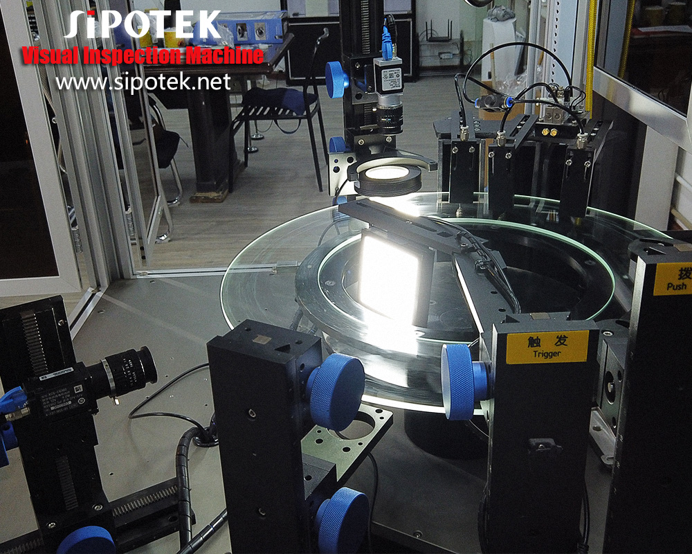
- Lighting Color
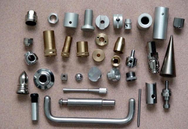
The color of lighting used for each particular part or application should be considered. The frequency is the number of shakes per second, and the wavelength is the distance between two points of the wave at the same position. Each of the different UV, blue, green, yellow, red, and infrared spectra has different illumination frequencies and wavelengths. These changes affect the response of the object and the surface of the camera as it enters. Its purpose is to utilize the frequency of light that produces maximum contrast and eliminates noise in the image. For example, metal parts can sometimes be introduced into a system that has a thin layer of oil or a slight oxidation of the surface, depending on how they are stored. When both types of parts are introduced into the inspection system, it is important to use the frequency of the light to reduce the amount of fluctuation.
- Use filter to eliminate serious environmental disturbances such as background and overhead lighting noise. Ambient lighting interference can be eliminated by simply placing a filter on the camera lens that matches the frequency of the light that illuminates the component.
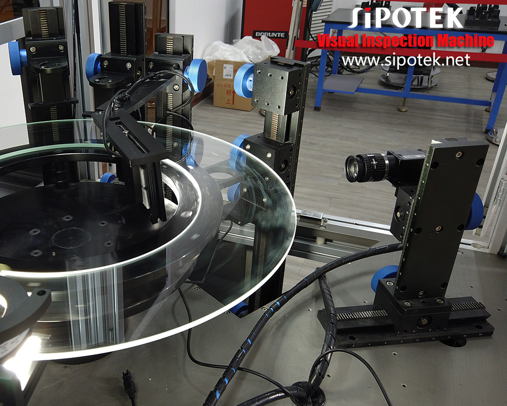
- Lens-field of view (FOV) and region of interest(ROI), including the required pixel accuracy
The correct focal length lens will determine the size of the area that the machine vision system can see and ultimately determine all the information collected and then do the calculation. Calculating a too large FOV will result in less detail and accuracy, while calculating a FOV that is too small may cause the check to fail because the part or object is outside the camera’s line of sight. When calculating FOV, it is important to determine the maximum ROI of the part or object and the maximum acceptable error for that area before deciding which focal length lens is best suited for the application. Sometimes these factors can be limited by the working distance or height of the camera to the object, so all these factors need to be considered before building the system.
It is important to know that the tolerances of the part or application are too big to allow repeated inspection of the part. When a component moves out of the camera’s view, it can cause system instability. Some type of physical fixture should be used to limit the motion of an object or part of interest. If the part moves out of the camera view, a failure can occur and add unnecessary downtime. This instability can be eliminated by providing a rough location of the part, ensuring that the part reappears in the machine vision system each time.
- Calibration
With a master fixture or calibration procedure, the system can be properly calibrated to ensure it meets the quality standards of the equipment.
- Features and benchmarks
In order to properly inspect the image and the benchmark, the unique feature found in each inspection can be used as a reference point for the vision tool during inspection, or to detect the presence of the correct portion of the image.
- Resolution
Resolution determines the repeat of the vision system. It quantifies the pixel size to a measurement data. The resolution of the system is important because it determines the accuracy and repeat of the inspection, especially on solutions for quality measurement testing and robot guidance. Some software can increase the resolution to sub-pixel accuracy.
- Stability
When setting up machine vision sensors, it is important to protect the camera system and lighting from movement. These items are the targets of system calibration. To minimize movement or interference, it is wise to place the camera and light where there is little or no vibration and traffic.

- Testing
Regularly check the system to see if defective parts are captured and rejected by the system. A test process can be built directly into the system to simplify the process. Defective test components can be placed into the system at any time to verify proper function of the system.
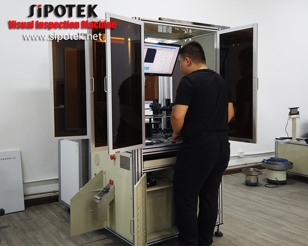
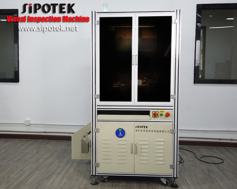
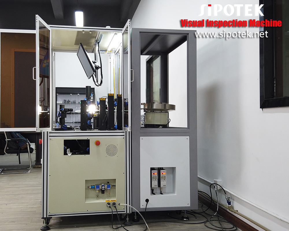
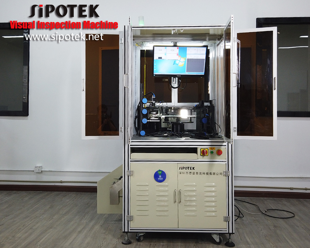
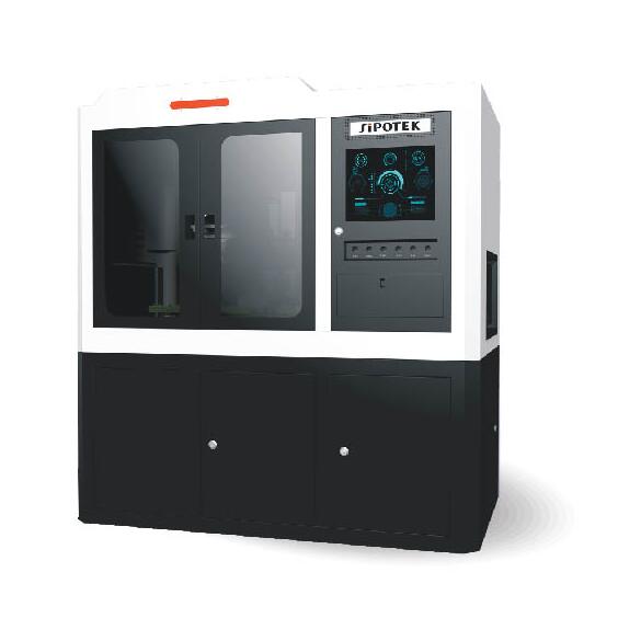
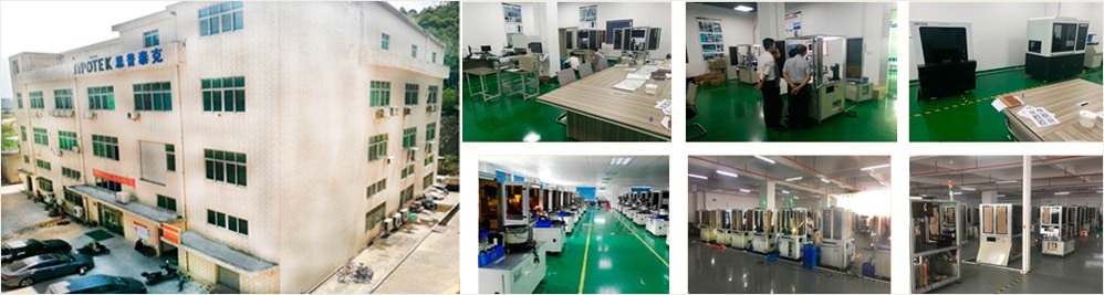
Established in 2002, Sipotek Technology is located in Shenzhen in China. The company designs and manufactures visual inspection systems with its avant-garde R&D department and a great experience in artificial vision technologies. Sipotek is a professional machine vision inspection system manufacturer from china.The Sipotek Technology staff supports customers 360 degrees automatd optical inspection(AOI), from listening to their requests to the development of ambitious machines for quality control.
For Media Inquiries:
Contact Person: James Yuan
Company: Shenzhen Sipotek Technology Co., Ltd
Tel: +86-18617182707
Email: [email protected]
Website: http://www.sipotek.net/